When thinking about the design of a building it is vital that rooflights are treated as an essential design consideration right at the start. That’s where we can help – delivering the right specification for the project in conjunction with the building owner, the designer or the consultant to help achieve a sustainable and energy efficient building.
This technical guide will outline key specification considerations and other related subjects
The provision of natural daylight within the built environment can deliver genuine, positive benefits to the finished construction; benefits that can enhance the financial and environmental performance of the building in service and improve the internal environment and make it a more pleasant place to be.
Natural daylight is associated with a whole range of positive effects on building occupants, from increased productivity and mental alertness to an improvement in general health. There is also anecdotal evidence of improved recovery times among patients in hospitals where the levels of natural daylight have been increased.
![]()
The Workplace (Health, Safety and Welfare) Regulations 1992 state: “Every workplace shall have suitable and sufficient lighting which shall, so far as is reasonably practicable, be by natural light.” As a purely commercial, project cost consideration, it’s completely free of charge.
All of which would point to natural daylight being the obvious principal consideration for the design of any building in which human beings are expected to spend any significant amount of time.
For any building, there is an optimum target percentage of rooflights which will deliver the optimum level of natural daylight into a building, making the optimum saving in energy usage and costs. Though solar gain can add to the energy consumption is powered cooling systems become necessary for instance. That is why it is important to properly consider a daylighting plan at the design stage of the building.
Glass reinforced polymer, known as GRP, it is produced by combining thermosetting polyester resin and short glass ‘rovings’ cut from continuous filaments.
Today there are a wide range of thermoset resins available for use with various glass fibre materials for all sorts of applications. From boat construction such as lifeboats, minesweepers and luxury yachts where high strength, durability and marine corrosion resistance is required, through to fuel and chemical containment tanks & pipelines; GRP materials find uses everywhere.
Thermoset materials, once cured, have very stable mechanical properties and are generally unaffected by heat unless this is sufficiently high to cause them to char or burn. This gives the characteristic of relatively low rates of thermal expansion and high durability leading to very long service life periods.
To improve the durability of GRP when used in outdoor applications and exposed to UV radiation and weathering, such as rooflights, the life of the material can be further prolonged by the application of a transparent surface protective film.
These characteristics make GRP an ideal product for use in rooflight panels and sheets. Especially where a material is required that can be moulded to match the profiles of the surrounding metal cladding sheets while benefiting from a high strength to weight ratio and extended service life.
The light that enters a building can be direct light such as that which passes through clear or transparent materials, or diffused light that is created by surface textures designed to create diffusion by surface refraction, or by materials that are translucent and naturally diffusing. Glass Reinforced Polymer (GRP) rooflights are manufactured using clear polyester resins reinforced with transparent glass fibres. As the light passes through the combination of materials, the light is scattered by refraction to create a diffusing medium.

Direct light
the building. For some applications, direct daylighting can offer positive benefits particularly in window applications, however in periods of strong sunlight it can create high contrasts between light and dark, undesirable shadows and glare.

Diffused light
When light is scattered as it passes through translucent diffusing materials such as GRP, or transparent materials that are modified to produce diffused light transmission, it does not necessarily reduce the levels of light transmission. It makes more efficient use of the available light by spreading it over a far greater area. This significantly reduces the apparent difference between light and shade and minimises the creation of shadows, thereby creating a more consistent and evenly lit space.
Retaining heat energy within a building to reduce carbon emissions has become a very high priority over recent years, and this has led to increasing insulation thicknesses and some changes in the way that buildings are constructed, specifically to minimise heat loss through the fabric of the building. This is not simply a key requirement of Building Regulations compliance. For building owners or tenants, it translates directly into a reduction in the running costs of a building due to increased energy efficiency.
In terms of heat retention, the energy efficiency of any element of a building is quantified by the U-value. This is a measure of the rate at which heat energy, measured in Watts, passes through a square metre of that element for every degree Kelvin difference in temperature from inside to outside, or outside to inside for refrigerated buildings. The U-Value is usually expressed as W/m²K. The lower the U-value, the better the thermal performance.
Rooflights by their very nature must allow the passage of the maximum amount of daylight whilst inhibiting the flow of heat. The most simplest and common method is the inclusion of insulation sing multiple layers of materials with high transparency.
There are now a wide range of insulation layer specifications for in-plane rooflights available, from simple Building Regulation compliant values of 1.8W/m²K to very low U-values of around 0.8W/m²K that can still retain excellent levels of light transmission.
Independent research by De Montfort University, and published by The Rooflight Association (RA), demonstrates the savings that can be made by the introduction of rooflights, and at larger areas than might previously have been considered optimum areas even with the most modest U-value performance.
Some light and heat energy passes directly through transparent and translucent materials, but there will always be a part of this energy that is reflected from the surface, known as reflectance, and a part that is absorbed by the material, known as ‘absorptance’.
The energy that is absorbed by the material is converted to heat and re-radiated both internally and externally. The greater the mass of the rooflight assembly or material generally, the greater is the capacity for heat build-up and re-radiation. This is referred to as the ‘secondary’ component in solar heat gain.
The combination of the directly transmitted heat energy and the re-radiated secondary component is referred to as the total solar transmittance, or g-value.
The primary reason for including rooflights into a building is to allow the entry of natural daylight and to take advantage of all of the benefits associated with it. It is also worth considering that a well designed building with a good spread of natural daylight will also benefit from passive solar gain that can reduce the demand for space heating for many months of the year.
Reducing solar gain and the risk of overheating would normally only be considered where people might be occupying or working in a certain part of the building for a substantial part of the day. It is not a requirement for areas not expected to be occupied for any duration such as circulation spaces, store rooms, toilets etc. Due to stratification in high or double-height industrial buildings, and accumulated dirt on rooflights combined with internal absorption, the impact of solar gain in occupied space is often reduced, justifying an increase in rooflight area.
Reliable data on internal gains for typical warehouse buildings is difficult to obtain, but a figure of 5W/m² is widely accepted. This value is entirely attributable to artificial lighting.
 It is important that the design from the outset, takes into account the buildings use to make sure the correct rooflight ratio and insulation is used.

Acoustic or sound transmission considerations in building design cover the methods by which sound can be transferred from one part of a building to another, or from inside to out and vice versa.
The interest in building acoustic performance has seen an increase in recent times, and particularly in respect of amendments to Building Regulations and Part E. The regulations focus on reducing the sound transmission through walls and floors, there are no specific requirements for roofs or rooflights.
Hambleside Danelaw carried out independent laboratory testing of airborne sound transmission through in-plane glass reinforced polymer (GRP) rooflight panels in accordance with BS EN ISO 140-3 and BS 2750-3.
The airborne sound transmission through the rooflight panel samples was determined by measuring the corrected difference in sound pressure between two reverberant rooms, the ‘source room’ and the ‘receiving room’. Noise levels over a wide range of frequencies were originated in the source room and then measured on both sides of the sample.
From these measurements the Sound Reduction Index can be calculated. This kind of laboratory testing is the only method that can measure the performance of a construction element accurately. Once materials are installed and in use in a building, other areas and attributes of the building can influence the actual sound transmission performance and create false results.
The performance and reaction of buildings in situations where fire breaks out is heavily dependent upon the way in which a building is designed, and the materials from which it is constructed. There are some key considerations that should be taken into account; everything from restricting the way in which fire can propagate and spread, to providing safe access routes so that the occupants of the building can escape to safety.
While the regulations relating to fire are constantly under review, the current Fire regulations document can be found in our downloads section.
The document sets out the requirements from the Building Regulations for England, Wales and Northern Ireland, and Technical Standards for Scotland including the required fire performance classifications whether using the BS 476 or BS EN 13501 Standards.
Further information is provided on the behaviour of GRP rooflights in fire situations with advice on their use in conjunction with sprinkler systems.
In the building life cycle embodied carbon are the emissions caused by extraction, manufacture, transportation, assembly, maintenance, replacement, deconstruction, disposal and end of life aspects of the materials and/or systems that make up a building.
Whenever figures are quoted for embodied carbon they are cradle-to-grave, or cradle-to-cradle wherever possible, so that you get the full picture.
All of our embodied data has been independently verified by Dcarbon8 and RPS Group.
Cradle-to-Grave
Cradle-to-grave is the full Life Cycle Assessment from resource extraction ‘cradle’ – through processing, manufacturing and use to final disposal phase – ‘grave’. This includes all packaging, transport and maintenance.
The quoted figures also make an allowance for transporting the rooflights to site, their maintenance in line with recommendations and the disposal of the rooflights after the building is demolished. Transport emissions can make a big difference to the embodied carbon especially when goods are moved across the globe.
Zenon Insulator cellulose acetate honeycomb core is extracted from tree fibres and is processed into a film which we make into honeycomb. At end of life it can be composted. This results in a very low embodied carbon figure of 0.28kg of embodied carbon per square metre of our 20mm thick insulation compared to the comparable thermal performance of 10mm thick, four-wall polycarbonate with 18 times the amount at 5.1kg.
Zenon Evolution factory assembled rooflights have significantly less cradle-to-grave embodied carbon of a traditional rooflight with the same performance over the lifetime of a standard building.
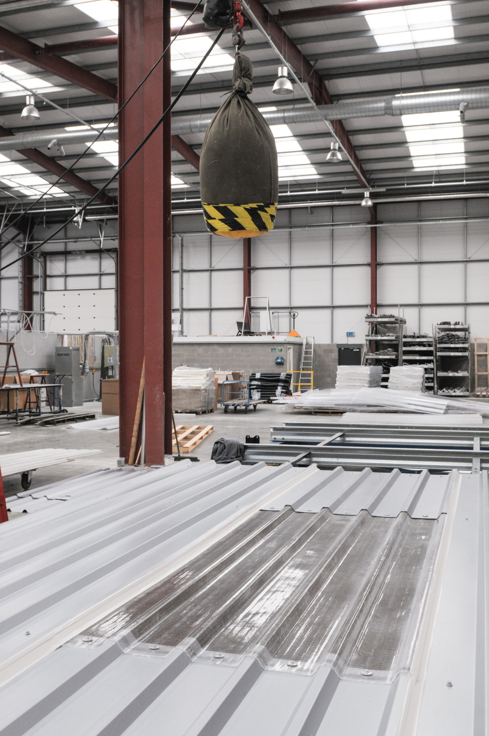
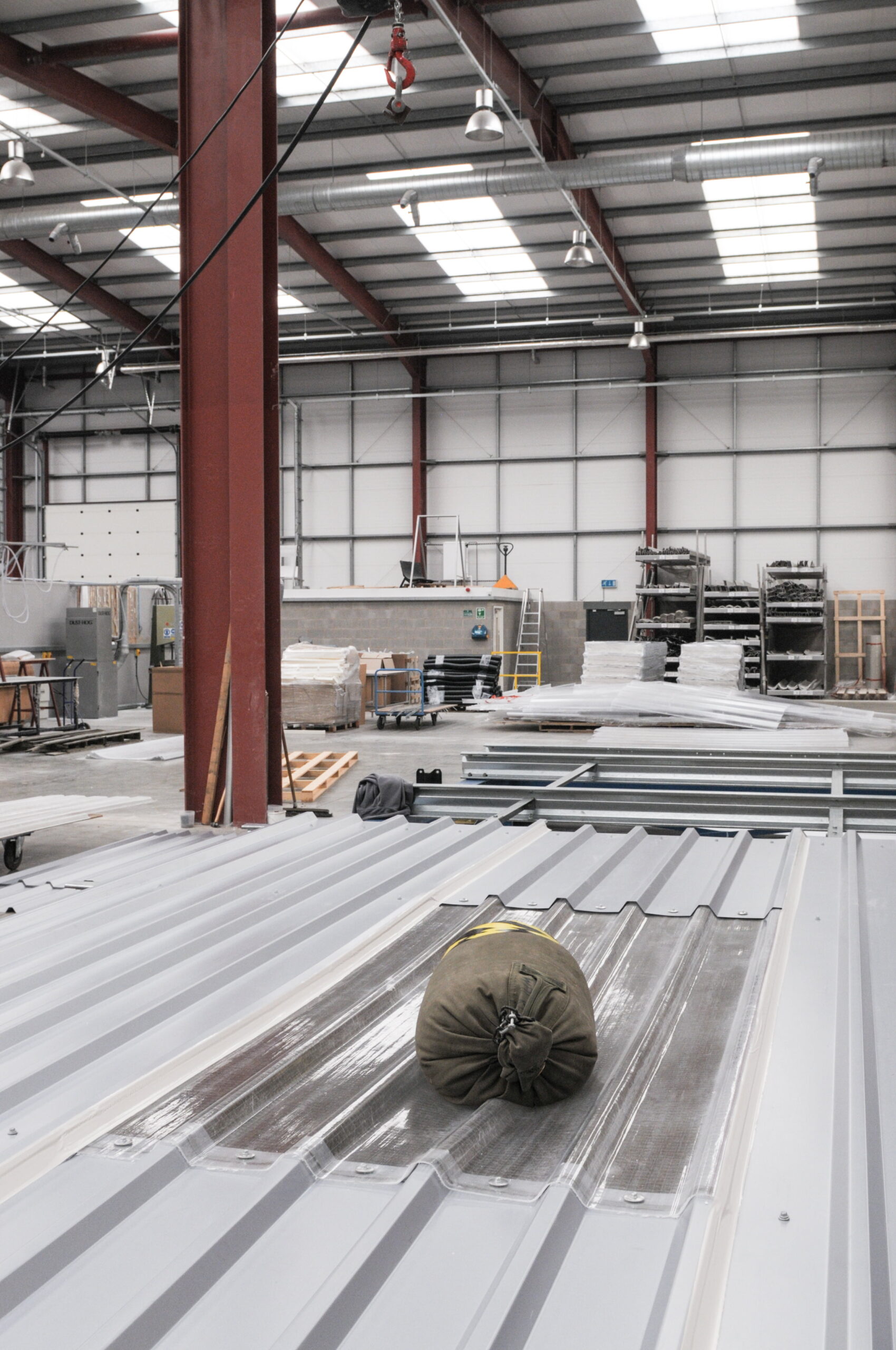
Before the publication of the first edition of ACR[M]001 by the Advisory Committee for Roof Safety in 2000, there was no clear guidance of how manufacturers and installers of systems could demonstrate that the requirements for non-fragility of roofs were being met…
The current edition of the ACR[M]001 Test for Non-fragility of Large Element Roofing Assemblies, often referred to as the “Red Book” prescribes how a representative roof assembly should be tested to demonstrate its ability to resist the impact of a person falling onto it, and then supporting their weight.
According to the ACR document, an assembly can be classed as either fragile or non-fragile. The test covers all components including all of the fasteners, sealant tapes etc – that are required to be representative of the finished installation.
The Test Procedure
The test should be carried out by a competent person. It involves an ‘impactor’ comprising a 300mm diameter cotton weave sandbag filled with 45kg of soft sand, being dropped from a height of 1.2 metres onto the roofing assembly.
The test sample is built on a standard roof rig representing a typical metal roof structure one metre high from the ground.
The impactor should be dropped in specific worst-case scenario zones, depending upon the assembly, where are generally:
- Within 150mm of the centre of the sample.
- Within 300mm of a support point.
- Within 150mm of the assembly edge, adjacent to the underlap with the next sheet.
- Where ever the competent person deems the worst-case scenario to be.

Classification of Results